Ball Mill

What are the uses of a ball mill?
Whatsapp/Wechat:
+86-13676922906
  • WhatsAppWhatsApp
  • WeChatWeChat
15s Quick consultation
1h Technical guidance
32h Quotation + drawing
365d Exclusive customer service

What are the characteristics of a ball mill?

1. Structural Aspects:

(1) Discharge Method: Wet ball mills can utilize overflow, grate, or peripheral discharge; wet rod mills primarily use overflow discharge but can also use peripheral discharge; dry ball mills mainly use grate or peripheral discharge; dry rod mills typically use only peripheral discharge.
(2) Internal Structure: To ensure the steel rods remain essentially parallel to the mill's axis during operation and to prevent rod tangling, the inner liners of the rod mill's feed and discharge end caps form a plane perpendicular to the cylinder; in contrast, the liners in ball mills are generally conical, though flat surfaces are also used.

2. Parameters and Performance:

To prevent interference between steel rods, rod mills generally operate at speeds of 65%–70% of the critical speed (nc); wet ball mills typically operate at 76%–88% of nc, while dry ball mills operate at 68%–76% of nc.nc: Critical speed of the mill;

3. Applications:

Because the contact between the grinding media (rods) and the material is linear, rod mills offer selective breakage and grinding, minimizing the risk of over-grinding; the upper limit of the discharge particle size is generally 1–3 mm, making them suitable for coarse grinding.

Compared to overflow-type ball mills, wet grate-type ball mills feature a discharge grate plate that actively lifts material for discharge; this results in a lower liquid level within the cylinder, a shorter material residence time, and a coarser discharge product. The upper limit of the discharge particle size for grate-type ball mills is generally 0.2–0.3 mm.


Wet Ball Mill vs Dry Ball Mill Specifications

Technical Feature / ParameterWet Ball Mill Dry Ball Mill 
Working PrincipleMaterials are ground with water or liquid to form slurry.Materials must be completely dry before entering the mill.
Moisture ContentHigh moisture / liquid environment allowed.Strictly ≤ 1% to ≤ 2% to prevent clogging.
Discharge MechanismOverflow type or Grate type (Slurry flow).Grate type with air-assisted wind sweeping system.
Grinding EfficiencyHigher (20% - 30% higher than dry type).Standard (Limited by material cushioning effect).
Particle FinenessFiner and more uniform particle size distribution.Slightly coarser (Fines may cushion the balls).
Energy ConsumptionLow power consumption per ton of material.Higher power consumption due to air transport systems.
Auxiliary EquipmentSlurry pumps, hydrocyclones, thickeners.Dust collectors, cyclones, air classifiers, fans.
Wear of Grinding MediaHigher chemical corrosion + physical wear.Pure mechanical wear (No corrosion).
Environmental ControlNo dust pollution, easy management on site.Generates dust; requires high-quality air filtration.
Best Application FieldsMineral Processing, gold/copper ore dressing, metal mining.Cement production, ceramics, chemicals, fireproof materials.

Whether you are looking for a heavy-duty cement ball mill for industrial manufacturing, a wet ball mill for mineral processing, or a small ball mill for pilot testing, Zhongxin is your premier ball mill machine manufacturer. Our industrial ball grinding mill series is engineered for durability and efficiency. Contact us to get the latest ball mill price list and upgrade your ball mill plant grinder system today. Get Ball Mill For Sale Details & Price List!
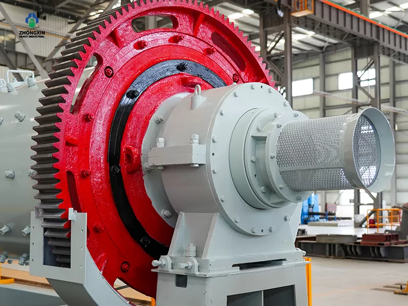
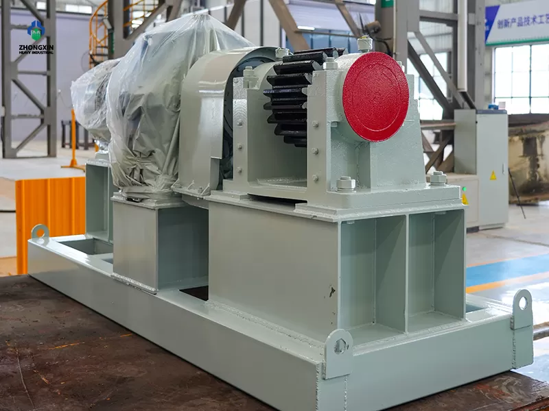
Differences and Applications of Ball Mills and Rod Mills

What is the working principle of a ball mill?

The ball mill transforms coarse feed materials into finely ground products through a controlled cascading motion of grinding media inside a rotating drum. By combining impact energy with particle-to-particle attrition, it delivers precise size reduction, high processing efficiency, and reliable performance across a wide range of mining and industrial applications.

1. The mill's drive unit rotates the shell, and raw materials enter the shell via the feeding device;

2. As the shell rotates, the grinding media—driven by centrifugal and frictional forces—adhere to the inner wall and rotate along with it;

3. Once lifted to a certain height, the grinding media fall freely under gravity, impacting and crushing the material at the bottom;

4. The motion state of the grinding media (e.g., cascading, cataracting, or sliding) plays a crucial role in grinding efficiency;

5. Through these processes, the ball mill grinds the material into the required fine particles;

6. The ground material is discharged from the mill shell via the discharge device.
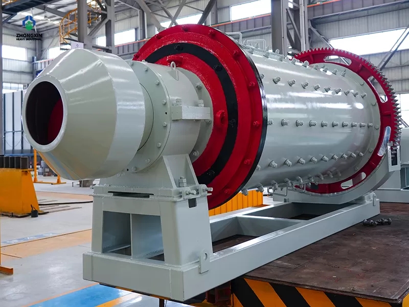
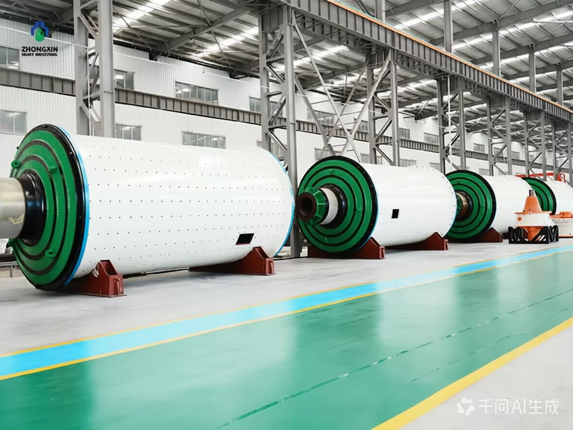
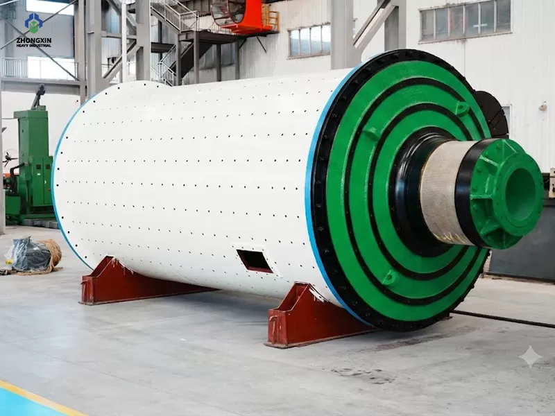
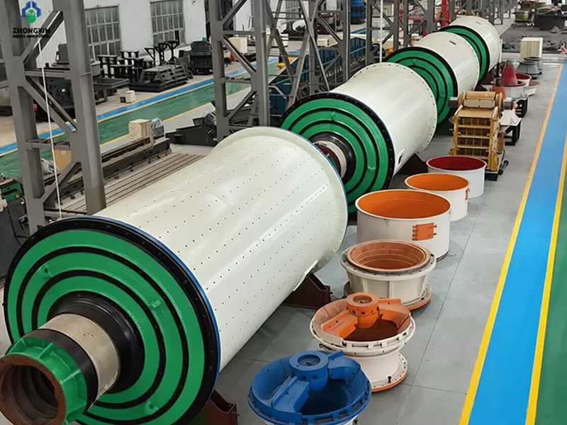
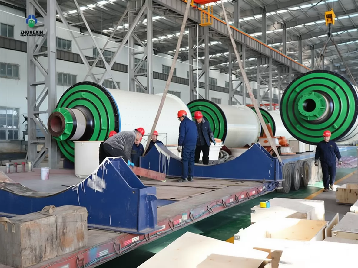
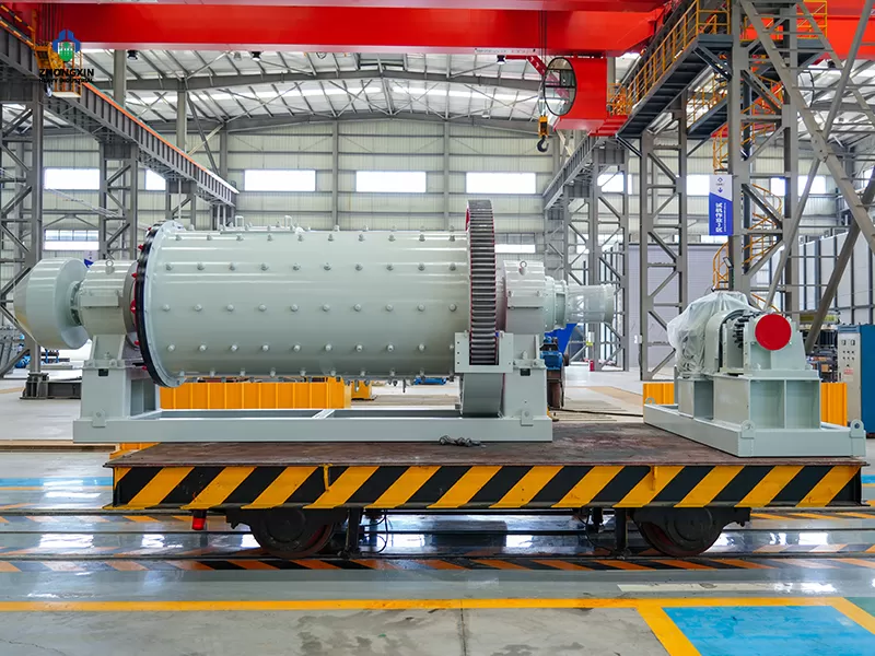
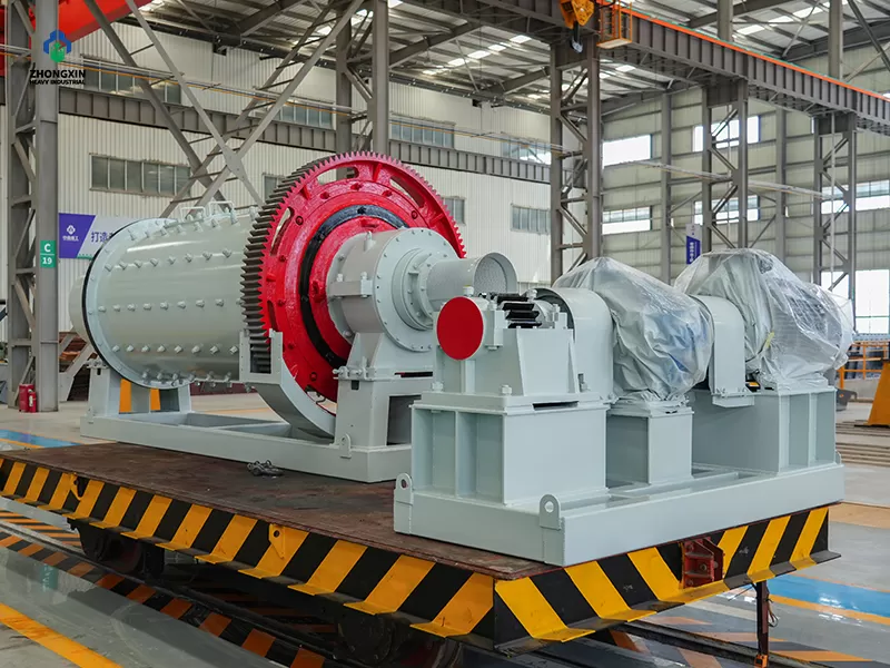
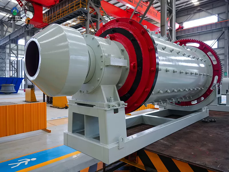
Ball mill grinding equipment manufacturing site overview

*La capacidad de producción variará en función de los distintos materiales, tamaño de alimentación y otros factores.

NumberModelCylinder diameter(mm)Cylinder length(mm)Cylinder effective volume(m³)Maximum ball loading(t)Operating speed(r/min)Main motor power(kW)
1MQ-09×18900900~18000.45~0.90.96~1.934.8~39.57.5~15
2MQ-12×2412001200~24001.1~2.22.4~4.729.8~33.922~45
3MQ-15×3015001500~30002.2~4.54.7~9.726.5~30.155~90
4MQ-21×□21002200~40007~1215~2722.3~25.3140~250
5MQ-24×□24002400~450010~1821~3920.8~23.6210~355
6MQ-27×□27002100~540011~2823~5919.6~22.2260~630
7MQ-32×□32003000~640022~4746~9817.9~20.4500~1120
8MQ-36×□36003900~700036~6475~13516.9~19.21000~1800

Caso Relacionado

Más >

FAQS

Our ball mills feature optimized liner designs and precision-engineered gear drives. This results in higher grinding fineness and lower energy consumption per ton, helping mining operations achieve better mineral recovery rates.

Ball mill specifications are typically designated by shell diameter and length. The ball mills manufactured or planned by our company fall into the following diameter (D) series (in mm): 900, 1200, 1500, 1830, 2100, 2400, 2700, 3200, 3600, 3800, 4000, 4200, and 4500; Ball mill length is usually selected within the range of (1–3)D. The diameter series for dry-type tube mills also includes sizes such as 2200, 2600, and 3000, with a shell length generally ≥3D.

1. Raw material characteristics: including ore type, hardness, content of major elements, etc.; 2. Particle size: initial particle size, crushed product size (mill feed size), and ground product size; 3. Availability of an ore grindability test report; 4. Availability of Bond Work Index data (determined via Bond Work Index testing).

1. Shell diameter and length: These are the primary parameters specifying the ball mill's size. Shell diameter refers to the internal diameter excluding the liners, while shell length refers to the effective internal length. 2. Effective shell volume: This is the internal volume of the shell minus the volume occupied by the liners. 3. Ball mill type: This primarily refers to the discharge method. 4. Maximum grinding media charge or media filling rate. 5. Operating rotational speed of the ball mill. 6. Installed power of the ball mill.

1. Feeding Section (Feeding Device) Common types currently in use include: drum feeders, combined feeders, chute feeders (feeding trolleys), and screw feeders. ① Drum Feeder The drum feeder resembles a drum open at both ends and features internal spiral components for conveying ore. As the feeder rotates along with the ball mill, the ore is transported into the mill following the spiral path. Drum feeders are suitable for feeding dry materials into the ball mill. ② Combined Feeder The housing of the combined feeder features an inlet and an outlet on its front and rear side plates, respectively. It is characterized by an internal partition plate that divides the housing cavity into an inlet chamber and a guide chamber. Feed-through holes are distributed along the periphery of the partition plate, while a cylinder is positioned at the center of the guide chamber, with its axis aligned with the outlet. A spiral guide plate is installed between the central cylinder and the housing within the guide chamber, and material-transfer openings are provided on the cylinder wall on the inner side of the spiral guide plate. This ingenious and rational design allows for the intake of larger lump materials and maintains a high material level within the mill. It prevents material backflow or spillage, reduces labor intensity, avoids pollution, increases feed capacity, and enhances productivity and profitability. It can handle both dry ore and wet materials (such as classifier underflow/sand returns) and is frequently used in the first stage of closed-circuit grinding. Additionally, because the combined feeder facilitates the addition of steel balls into the ball mill, it is also utilized in second-stage grinding circuits. Overall, the combined feeder is widely applied. 3) Screw Feeding Device The screw feeding device is a common feeding method for dry mills and wet grinding mills. It primarily consists of an enclosed screw feeder, a hopper, and a support structure. Equipped with a motorized drive unit, it functions as an active (powered) feeding system. ④ Chute-type feeding device The chute-type feeding device is a common feeding method for large-scale mills, characterized by its simple structure and ease of replacement. It primarily consists of an inclined pipe, a sealing assembly, a hopper, and a support mechanism; the support mechanism is sometimes designed as a movable trolley to facilitate inspection and maintenance. 2. Feeding section: Composed of the feed end cover, end liner, and feed bushing. 3. Shell section: Composed of the shell (fabricated by welding flanges to a rolled steel plate cylinder) and shell liners; the shell is equipped with one or two manholes for liner replacement. 4. Discharge section: Available in overflow and grate types. The overflow type consists of the discharge end cover, end liner, and discharge bushing; the grate type consists of the discharge end cover, discharge grate plate, inner liner, and discharge bushing. A cylindrical discharge screen is sometimes added to the discharge section. 5. Support section (also known as the main bearing section): Features either rolling bearings (typically spherical roller bearings) or sliding bearings. 6. Drive section: ① Asynchronous motor drive: The motor drives the speed reducer via a coupling; the low-speed shaft of the reducer then drives the pinion gear via a coupling, which in turn drives the large gear. ② Synchronous motor drive: The motor drives the pinion gear via a clutch, which in turn drives the large gear. 7. Slow-speed drive device: Composed of a motor, brake, high-ratio speed reducer, helical-tooth clutch, etc. 8. Shell lifting device: Composed of a lifting bracket, a jack, and a support stand. 9. Lubrication system: Divided into grease lubrication and circulating oil (fluid oil) lubrication types. 10. Cooling system 11. Foundation 12. Electrical control system

1. By drive mechanism ① Peripheral drive The drive unit rotates a pinion gear, which drives a large gear to rotate the mill shell. ② Center drive The drive unit connects to the mill's discharge end cap (or feed end cap) via a coupling, directly driving the rotation of the mill shell. ③ Friction drive The drive unit powers a supporting friction wheel, which drives the rotation of the mill shell. 2. By discharge method ① Grate-discharge type A grate plate is installed at the discharge end; material smaller than the grate apertures passes out of the shell, while material larger than the apertures remains inside for further grinding. ② Overflow type Material discharges by overflowing when the pulp level rises above the lower edge of the hollow trunnion opening. To prevent small grinding balls and coarse material from escaping with the pulp, the discharge liner is equipped with reverse spiral blades that push them back into the shell. ③ Peripheral discharge type Discharge ports are located along the circumference of the mill shell and fitted with grate plates to prevent the discharge of grinding media and coarse material. 3. By grinding media ① Ball mill: Uses balls of varying diameters (matched in specific proportions) as grinding media; particle size reduction is achieved through the impact and collision of the balls. ② Rod mill: Uses steel rods of varying diameters (matched in specific proportions) as grinding media; particle size reduction is achieved through the impact and collision of the rods. ③ Autogenous mill Relies entirely on the ore itself as the grinding medium. Large ore chunks are lifted to a certain height during shell rotation and then fall freely, achieving breakage through impact and attrition; smaller particles are discharged through the outlet. Structural characteristics: Large shell diameter (up to 12 meters or more), relatively short length, and low rotational speed (approximately 70%–80% of the critical speed). ④ Semi-autogenous (SAG) mill: Similar to an autogenous mill, but with a small amount of steel balls (filling rate of approximately 8%–15%) added as auxiliary grinding media. The impact of the steel balls compensates for the limitations of the ore's inherent grinding capability, thereby enhancing processing efficiency and stability. 4. By grinding conditions ① Dry mill: Generally, the moisture content of the feed material is less than 2.5%; ② Wet mill: Grinding concentration is less than 75%; ③ Moist grinding mill: Generally, the moisture content of the feed material is between 8% and 15%. 5. By operating mode ① Continuous mill: Feeding and discharging occur continuously without interruption; ② Intermittent mill (also known as batch mill): Material is loaded once, processed for a specific period, and discharged only after the required particle size is achieved. 6. Others: For example, mills with a length-to-diameter ratio of 3 or greater are classified as tube mills, etc.

Over-grinding wastes energy and ruins product quality. To prevent this, you need to optimize the ball-to-material ratio and adjust the classification system (like a cyclone classifier) to remove qualified fines instantly. Our mills feature variable frequency drives (VFD) and smart PLC monitors, allowing you to fine-tune the rotation speed in real-time based on material moisture and feed size.

Wet grinding is generally 20% to 30% more energy-efficient than dry grinding because the liquid acts as a dispersant, preventing fine particles from coating the grinding balls. It also eliminates the need for expensive dust collection systems. However, if your downstream process cannot tolerate moisture (e.g., cement or chemical powders), dry grinding with a specialized air classification system is required.

Personaliza Su Solución de Trituración

Contáctenos rellenando el formulario o por Email: sales@zxcrusher.com

Full Lifecycle On-Site Maintenance & Overhaul

We offer turnkey on-site services ranging from installation guidance, girth gear flipping, and liner replacement to complete mill overhauls. Backed by specialized tools, our experienced service technicians ensure tasks are completed safely with minimal turnaround time to resume production swiftly.

Premium Wear-Resistant Spare Parts

We provide a comprehensive range of high-quality ball mill spare parts, including high-manganese/alloy steel liners, wear-resistant grinding balls, main bearings, and drive gears. All components undergo rigorous wear and impact testing to significantly extend equipment campaign life and reduce unscheduled downtime.

Grinding System Process Optimization & Upgrades

Beyond supplying parts, we focus on your overall plant profitability. By conducting comprehensive audits on process parameters like mill filling rate, ball charge seasoning, and classification efficiency, we deliver tailored upgrade solutions to help mines and cement plants cut costs and improve energy efficiency.
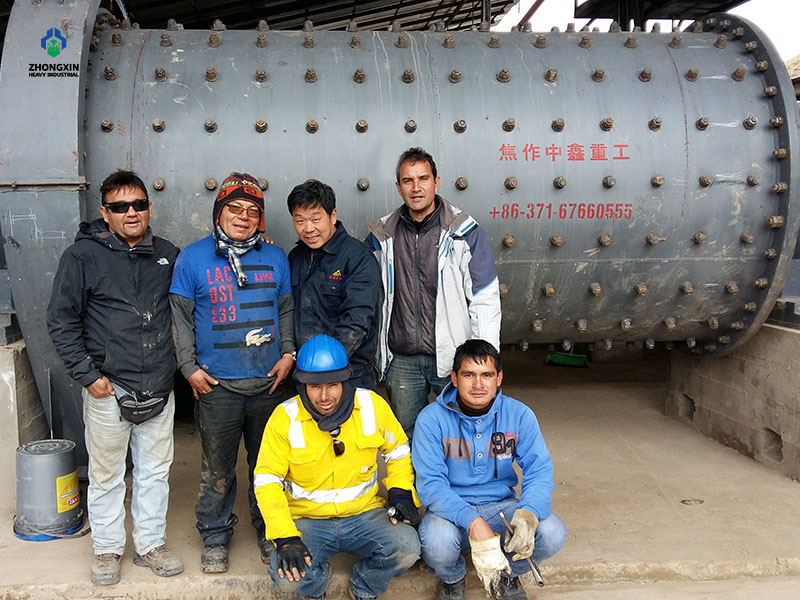
Industrial manufacturing

Lifecycle Services

We provide comprehensive support throughout the entire lifecycle of your equipment. Our service approach ensures long-term reliability and optimized performance for every project.